< Hi my name is Rodrigo, I'm from Zacatecas, Mexico. I started my university studies in the UTZAC in 2010. After 2 years, I obtained my first professional degree (Técnico Superior Universitario) equivalent to a BTS in France.
I obtained a scholarship to study in France for 1 year, my previous studies were re-validated by the Ministry of Education in France. I studied a "Licence Professionnelle" (Bachelor's degree) named SARI (Industrial Nets and Automation) where I learned a lot of cool stuff, and I learned to speak french as well. A the end of the career, I had the opportunity to make an internship in a Nanotechnology Laboratory in Marseille France at the IM2NP. The details of the project are in this blog in a separate entry. Back in Mexico, I decided to continue my professional development, so I studied an Engineer degree, which I finished in December 2015. The vast majority of the projects shown in this blog were done while I was studying the Mechatronics Engineering career. On the other hand, I have professional experience too, I've been working in a information technology enterprise, Softtek, working as Information Security Engineer, for General Electric.
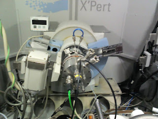
The objective of this work is to implement an interface in the LabVIEW environment for coupling three experimental characterization techniques (Reflectivity-diffraction-resistivity 4 point). This interface must allow to achieve the 4-point resistivity measurement (power steering and power reading via two Keithley devices) to control the temperature controller (Tectra-Micromega) and retrieve a temperature reading.
The tools available to me
Source courant
Model: Keithley 6220 Precision current source I used a power generator can deliver current 0.1pA - 105mA. This instrument communicates with the PC via the GPIB protocol (General Purpose Interface Bus) also known as IEEE-488. The source communicates with the voltmeter simultaneously, using RS232 protocol (standard). To send the current source has a typical output triax, the source sends current directly on the sample.
Nano-voltimeter
Model: 2182A Keithley nanovoltmeter The voltmeter does not communicate directly with the computer, it communicates with the power source via the RS232 serial protocol, So we send the commands to the source, and the source sends commands to the voltmeter. The device has two Channel, Channel 1 and Channel 2, Channel 1 will use to read voltage, and Channel 2 to read the temperature (see Figure 7).
Channel 1 is used as a basic measuring channel, while Channel 2 provides common sense measures. Because of this operative relationship between the two channels, the Channel 2 can not be used as an independent stand-alone measurement channel. Its inputs must be referenced on Channel 1 LO.
Temperature Controller
It is necessary to create an interface to control the temperature of the furnace, the device used is temperature controller Tectra Micromega-CN77. The instrument communicates with the computer, it uses a RS232 cable. The controller has two outputs, output 1 and 2, only output 1 is used, the controller sends a direct current to heat the furnace. To control temperature, it must have feedback, a type K thermocouple is used for this, which is placed directly on the furnace. Temperature control is done by the instrument itself. The interface only gives the set to go up at certain temperatures in a certain time (set to perform a temperature ramp, a landing, or isothermal). Below images show the connections between the PC, controller, thermocouple "furnace" and multi-room characterization.
The Internship Mission
The mission is to create a program in which the three devices must be controlled at the same time in this program we will look at an XY graph that will map the electrical resistance measured over the sample temperature. At the end of each experiment, will recover the reading of current, voltage, resistance and temperature of the sample in a TXT file. It does not measure the resistance, it is calculated by Ohm's law..
Voltmeter current-source interface
There 3 configurations for the current generator:
1.The first configuration: Applying a constant current "ICST" for the duration of the experiment. To report how long will the experiment, there is a choice between a specific time, for example 60 minutes, or by points of reading, for example, read 300 points, every 10 seconds.
2. Second configuration: it is a measurement made in the sample being heated, with a change in current to a preset temperature.The initial current is applied at low temperature, it corresponds to I1;
There are 3 important parameters in this configuration: I1, I2 and TL. When the sample gets to a temperature greater than TL (limit temperature) we will apply a current I2. The current I2 will be applied until the end of the experiment.
3. Third configuration: it is to make a current ramp "I Ramp" .There are 3 parameters: initial I, I incremental (step) and I final. The current will rise gradually until the I final, and it is also necessary to control time step.
In Below image you can see the source code for the first configuration: for the constant current.
Temperature-controller interface
As stated before, we do not control the temperature on labVIEW, the controller does himself. What we will do is to give instructions to the controller, and recover the temperature in the sample read by the thermocouple. It should also create a program to change the controller settings, the type of PID control or on / off, depreciation, etc. For the purposes of the experiment, it must be a ramp, a plateau and a fall in temperature.
1. A ramp with T1 (initial temperature), T2 (final temperature) and the step (the rise in degrees, with a step fixed).
2. A bearing, it will maintain the temperature for a specific time.
3. Lowering the temperature: it starts with the bearing temperature and ends with T3. It must also set the time during which the temperature goes down and how many degrees it will decrease each time.
For descent, can not cool the furnace, thus it cools itself, but can be slowed down while maintaining the temperature at a programmed value during some time.
The Details of this project can be downloaded from this link The source code of the program can be downloaded here
A field-programmable gate array (FPGA) is an integrated circuit designed to be configured by a customer or a designer after manufacturing – hence "field-programmable". The FPGA configuration is generally specified using a hardware description language (HDL), similar to that used for an application-specific integrated circuit (ASIC). (Circuit diagrams were previously used to specify the configuration, as they were for ASICs, but this is increasingly rare.)
A Spartan FPGA from Xilinx
FPGAs contain an array of programmable logic blocks, and a hierarchy of reconfigurable interconnects that allow the blocks to be "wired together", like many logic gates that can be inter-wired in different configurations. Logic blocks can be configured to perform complex combinational functions, or merely simple logic gates like AND and XOR. In most FPGAs, logic blocks also include memory elements, which may be simple flip-flops or more complete blocks of memory.
Project objective
The objective of this project is to create a sequence for a robotic arm trough the FPGA card,
the robot should take 4 pieces in a store and put them in a pallet.
The robotic arm has 5 joints, each joint is moved by a DC motor,
A L293 D Integrated Circuit was used as H bridge in order to move the DC motors forwards and backwards. The integrated circuit also is used as power stage.
The integrated circuit can manage 2 motors in both directions, as the robotic arm has 5 motors, 3 integrated circuits were used in this case, you can see the final connection in a protoboard in below image.
---------------------------
-- Robot Control
-- Rodrigo Romo
-- Sistemas Digitales
-- UTZAC
-- Aug 12 2015
---------------------------
library ieee;
use ieee.std_logic_1164.all;
use IEEE.STD_LOGIC_ARITH.ALL;
use IEEE.STD_LOGIC_UNSIGNED.ALL;
entity wep is port ( a,b,c,d,clk: in std_logic; q,r,s,t,u,v,w,x,y,z: out std_logic );
end wep;
architecture narf of wep is
signal counta :integer:=0;
signal countb :integer:=0;
signal countc :integer:=0;
signal countd :integer:=0;
begin process (a,b,c,d,clk) begin if ( clk' event and clk= '1') then if (a= '1') then -- Figura 1 counta <= counta + 1; if (counta < 5) then – w8 q <= '0'; r <= '0'; elsif (counta >= 5 and counta < 21)then -- moves anti clockwise q <= '1'; r <= '0'; elsif (counta >= 21 and counta <27) then -- w8 q<= '0'; r<= '0'; elsif (counta >= 27 and counta <30) then -- motor 3 up u<= '0'; v<= '1'; elsif (counta >= 144) then counta <=0; q<='0'; r<='0'; s<='0'; t<='0'; u<='0'; v<='0'; end if;
The project objective
is to create and design a manual control stage for a robotic arm CRS A255, the robot
has 5 degrees of freedom. Originally the robot was controlled by a computer,
working as power stage and control stage with his own programming language. The
computer was damaged some years ago, the robotic arm has been useless for a
long time in the manufacture laboratory at the university.
The idea is to create
a power and control stage through a source power, control box, with their own
circuits and a connections box to get the robot in function, and this way it
can be used for future projects.
Robot Components
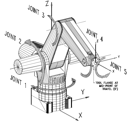
The A255 arm has five joints or axes, providing five degrees of freedom. This allows the arm a forceps or other tool to spatial Cartesian coordinates and orientation move defined by X, Y, Z, Z-rotation, Y-rotation, X rotation.
The A255 robotic arm has 5 degrees of freedom (joints). Each joint except the former has a brake which prevents movement of the robot by gravity when the motors are not running, in other words the brake prevents the robot moves by its own weight. Before moving joints 2,3,4,5 should disable their brakes and brake must be activated at the end of the movement.
As an initial step we proceeded to remove the casing of the robot with an Allen wrench, to review the components and connections thereof. motors that were exposed on the lower image correspond to the joints 2 and 3. In the rear of the robot motors you find joints 4 and 5. The motor of the joint 1 is in the inside of the base.
We can see in below image the components of the joint number 3, from right to left:
Encoder, motor and brake.
The movement of the joints is caused by a servomotor, between higher the voltage applied to the greater will be the motor torque and motor speed. By changing the polarity connections in the motor rotates to the opposite direction.
The encoder is a device that allows us to measure the degree that it has moved the motor. It is a very precise device. The operation of the encoder is outside the scope of this project however may be used in future projects.
CHECKING THE ELECTRIC MOTORS OF ROBOT
The objective of this stage is to ensure that each robot servo function correctly. For this robot housing removed exposing its internal connections, then with an external power source is energized each of the cables with different voltages (V).
The following conclusions were obtained:
1. The brakes have no polarity
2. The brakes release at least 10 volts.
3. If the same 10 volts applied to the motor, it move too fast.
4. Agreed to manipulate the motors with a voltage of 5 volts for testing.
5. A cable of each motor and each brake are connected in common.
As a result the number 5 in the previous section, the following problem is created. How to activate the brakes and the motor 10 volts to 5 volts having a common cable?
As first approach it was thought to introduce a new cable in order to have the connections separated and working independently, this is a challenge because you would have to change the physical structure of the robot, without mentioning that would completely disarm which is very difficult.
A subtraction of the voltages was proposed as solution. The Brake does not have polarity does not matter if we apply what part of the positive voltage must be applied at least 10 volts to deactivate the brake, depending on the applied voltage an polarity the motor will rotate at different speeds and directions.
Two current sources were used to feed independently the motor and brake. A H bridge is used to change the polarity to the motor supply and thus the sense of direction of the motor as shown in the figure below.
A H bridge is an electronic circuit that enables a voltage to be applied across a load in either direction. These circuits are often used in robotics and other applications to allow DC motors to run forwards and backwards.
5 H bridges in a protoboard in order to test the robotic arm.
Testing the robotic arm with the H bridge. The robot worked well with the proposed solution.
The next step is to create a PCB board.
CNC stands for computer numerical control.CNC routers can perform the tasks of many carpentry shop machines such as the panel saw, the spindle moulder, and the boring machine. They can also cut mortises and tenons. A CNC router is very similar in concept to a CNC milling machine. The objective of this project is to create the Marlboro logo in a plastic piece. The model was taken from bellow image.
The machine used is a eXpertMill VMC-0600
The software to program the machine CNCBase for intelitek CNC & Fanuc emulator.
This project consist in create an automatic control for the motion of an object A in relation with an object B . The object A is a plastic piece and object B is a CNY70 proximity sensor, the sensor is fixed, the movement of the plastic piece is induced by a DC fan.
The project objective is to set the plastic piece at a distance X, this value is entered in the computer via an interface created in LabView, this distance should not vary if the structure moves, the fan speed is automatically adjusted so that the distance X is always the same.
The tools available to me
CNY70 Sensor
The CNY70 is a short range infrared sensor based on a light emitter and a receiver, both pointing in the same direction and whose operation is based on the reflectivity of the object and the reflected ray detection by the receiver.
Arduino Card (Data acquisition)
In this project the Arduino is used as an interface between the computer, and input and output signals, The A0 pin is used to read the analog signal CNY70 sent by the sensor and the A1 pin to send analog signal to the fan.
Analog Signal acquisition
As already mentioned CNY70 reflective optical sensor is used to measure the distance between point A and point B. The sensor is supplied with a voltage of 5 V in the terminals 1 and 4 as shown in the diagram The pin 2, the cathode of the infrared LED is connected to a 330 ohms resistance and to ground. The Pin 3, the emitter of phototransistor is the output signal. The Arduino reads this signal
between 0 and 5 V, and it is interpreted as a distance.
To adjust the analog sensor signal that is sent to the Arduino card, a potentiometer was used and it was calibrated to send the signal as high as possible when the fan is at maximum power.
Reading the analog signal from the card
The analogue signal goes from 0-5 v, the Arduino board interprets this information and stores the value in a integer type variable. Arduino reads the value of the specified analog pin. The Arduino board contains a 6 channel, 10-bit analog to digital converter. This means that it will assign input voltages between 0 and 5 volts into a variable between 0 and 1023 . This produce a resolution of readings of: 5 volts / 1024 units or 0.0049 volts (4.9 mV) per unit. It takes 100 microseconds (0.0001 s) to read an analog input, so the maximum read rate is approximately 10,000 times per second.
The code used is as follows:
Arduino
int dato0 =0;
int wep=0;
void setup()
{
Serial.begin(9600);
}
void loop()
{
dato0 = analogRead(0);
wep = dato0;
Serial.println(wep);
delay(100);
}
Labview code:
Signal interpretation by LabVIEW
LabVIEW can read information by serial protocol thanks to the NI VISA library. The information is sent by a USB cable and use the serial protocol; An arrangement was made in the program because the sensor sends a weaker tension as far is the body B, and wanted to get the opposite behavior, to obtain a higher voltage when the distance between the sensor and the object is bigger. This was achieved by multiplying the signal by -1 then adding 700 units, to set to 0 when the object is at rest, it was finally divided between 139.2, thus when the object is at rest reading the signal displays 0 volts and 5 Volts when the fan is at maximum power.
Sending the analog signal from LabVIEW to Arduino.
The motor control is done by Labview; LabVIEW sends a digital signal
through the serial port to the Arduino board. The Arduino board has a range from zero
up to 254 bits in serial port, with 0 bits being equivalent to 0 V. and 254 bits to 5 volts.
A range between 0 and 5 to display in the graph was established, with 0 being the fan off and 5
maximum power. In below graph the voltage was changed manually by a numerical control in Labview
The arrangement that was made in the code was 254 (the maximum value in the range of 5 Card v) divided by 5, giving it 50.8 to vary the power output from 0 to maximum power.
It should be mentioned that you can only use integer variables for the serial protocol for the Arduino board, we can not send dual rate values for example 4.4 or 3.7. To solve this we use the range card that goes from 0-254 in its serial protocol, so if we want to send a signal of 4.4 volts, multiply 4.4 by 50.8, which results in 223.52, as we can not send decimals, we convert this value to an integer variable and a value of 224 interpret what the card is sent as 4.4 volts
Sending the signal from the Arduino board to the engine.
The Arduino board receives the digital signal via the serial protocol, converts it to an analog signal and sends it to the motor by the pin 3.
Here is the source code used by the Arduino board.
const int motor= 3; // *********** Sets variable motor to analog output 3
int speed; // ********** ********Variable for the motor speed
void setup () {
Serial.begin (9600); // ********** Speed for serial protol 9600 bauds
pinMode(motor, OUTPUT); // *** The variable motor is going to output the signal
}
void loop () {
speed = Serial.read(); // ********* Speed variable recieves signal from labview,
analogWrite(motor, speed); //***** Output speed value to the motor
delay(100);
}
This is the graph of the signal sent by the Arduino board to the motor 3 v.
Power Stage
The fan used was a direct current motor 12 v. The Arduino board can only supply 5 V maximum, so it was necessary to create a power stage for this, a TIP 122 transistor . The analog signal sent from the Arduino board is introduced directly into the base of the transistor, the collector is connected to the negative side of the fan. The emitter to the Arduino ground and 12 V source making a common ground. With this configuration when the card sends 5 V transistor passes 12 V in the source.
As shown in the graph, to send a signal of 5 volts, transistor let pass all power supplied by source 12 V and the engine will work at maximum power.
General Operation
The sensor sends a beam of light through the infrared LED, it bounces against the object plastic and is detected by the phototransistor, which interprets it as an analog signal, the farther the object, the smaller the signal.
The Arduino board receives the signal sent by the sensor in analog input A0, the analog signal is converted into a digital value, stored in a variable of type integer, and its sent to to the computer by serial protocol. .
Labview receives the value of the variable, and read every 100 milliseconds thanks to a while loop, as the signal is weaker if the subject is further away from the sensor, an arrangement was madewithin the LabVIEW program, to show in the graph a value of 0 if the plastic piece is at rest and a value of 5 if the fan is at its maximum power.
Labview compares the value of the actual distance to the desired distance, and makes a subtraction between both distances, this is known as an error, in the PID control, LabVIEW calculates how much must send the engine power to reduce the error to 0
Labview signal is sent by the serial protocol to the Arduino board.
The Arduino card converts the digital signal received by the by the Arduino protocol, converts into an analog signal, and sends it to the circuit via pin 3
The signal reaches the base of the transistor and depending on its intensity, certain current passessource 12 volts, and is sent to the fan..


