The objective of this work is to implement an interface in the LabVIEW environment for coupling three experimental characterization techniques (Reflectivity-diffraction-resistivity 4 point). This interface must allow to achieve the 4-point resistivity measurement (power steering and power reading via two Keithley devices) to control the temperature controller (Tectra-Micromega) and retrieve a temperature reading.


The tools available to me
Source courant
Model: Keithley 6220 Precision current source I used a power generator can deliver current 0.1pA - 105mA. This instrument communicates with the PC via the GPIB protocol (General Purpose Interface Bus) also known as IEEE-488. The source communicates with the voltmeter simultaneously, using RS232 protocol (standard). To send the current source has a typical output triax, the source sends current directly on the sample.


Nano-voltimeter
Model: 2182A Keithley nanovoltmeter The voltmeter does not communicate directly with the computer, it communicates with the power source via the RS232 serial protocol, So we send the commands to the source, and the source sends commands to the voltmeter. The device has two Channel, Channel 1 and Channel 2, Channel 1 will use to read voltage, and Channel 2 to read the temperature (see Figure 7).
Channel 1 is used as a basic measuring channel, while Channel 2 provides common sense measures. Because of this operative relationship between the two channels, the Channel 2 can not be used as an independent stand-alone measurement channel. Its inputs must be referenced on Channel 1 LO.

Temperature Controller
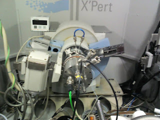
It is necessary to create an interface to control the temperature of the furnace, the device used is temperature controller Tectra Micromega-CN77. The instrument communicates with the computer, it uses a RS232 cable. The controller has two outputs, output 1 and 2, only output 1 is used, the controller sends a direct current to heat the furnace. To control temperature, it must have feedback, a type K thermocouple is used for this, which is placed directly on the furnace. Temperature control is done by the instrument itself. The interface only gives the set to go up at certain temperatures in a certain time (set to perform a temperature ramp, a landing, or isothermal). Below images show the connections between the PC, controller, thermocouple "furnace" and multi-room characterization.


The Internship Mission
The mission is to create a program in which the three devices must be controlled at the same time in this program we will look at an XY graph that will map the electrical resistance measured over the sample temperature. At the end of each experiment, will recover the reading of current, voltage, resistance and temperature of the sample in a TXT file. It does not measure the resistance, it is calculated by Ohm's law..
Voltmeter current-source interface
There 3 configurations for the current generator:
1.The first configuration: Applying a constant current "ICST" for the duration of the experiment. To report how long will the experiment, there is a choice between a specific time, for example 60 minutes, or by points of reading, for example, read 300 points, every 10 seconds.
2. Second configuration: it is a measurement made in the sample being heated, with a change in current to a preset temperature.The initial current is applied at low temperature, it corresponds to I1;
There are 3 important parameters in this configuration: I1, I2 and TL. When the sample gets to a temperature greater than TL (limit temperature) we will apply a current I2. The current I2 will be applied until the end of the experiment.
3. Third configuration: it is to make a current ramp "I Ramp" .There are 3 parameters: initial I, I incremental (step) and I final. The current will rise gradually until the I final, and it is also necessary to control time step.
In Below image you can see the source code for the first configuration: for the constant current.

Temperature-controller interface
As stated before, we do not control the temperature on labVIEW, the controller does himself. What we will do is to give instructions to the controller, and recover the temperature in the sample read by the thermocouple. It should also create a program to change the controller settings, the type of PID control or on / off, depreciation, etc. For the purposes of the experiment, it must be a ramp, a plateau and a fall in temperature.

1. A ramp with T1 (initial temperature), T2 (final temperature) and the step (the rise in degrees, with a step fixed).
2. A bearing, it will maintain the temperature for a specific time.
3. Lowering the temperature: it starts with the bearing temperature and ends with T3. It must also set the time during which the temperature goes down and how many degrees it will decrease each time.
For descent, can not cool the furnace, thus it cools itself, but can be slowed down while maintaining the temperature at a programmed value during some time.
The Details of this project can be downloaded from this link
The source code of the program can be downloaded here
No hay comentarios:
Publicar un comentario